
Electrical and Mechanical Instability Under Severe Environmental Stress
Challenge
A systems engineer supporting a long-life aerospace and defense program was tasked with delivering electronics capable of surviving extreme environmental exposure. The system would operate under repeated shock and vibration events, wide thermal cycling, vacuum transitions, radiation exposure, humidity excursions, and strict contamination control protocols.
The electrical design met initial performance requirements, but environmental testing began to expose weaknesses in the packaging platform. Over extended qualification cycles, the program encountered instability tied not to the active devices, but to the substrate and interconnect structure supporting them.
Failure mechanisms began to emerge:
- Electrical drift after thermal cycling due to material expansion mismatch
- Micro-cracking and metallization fatigue under vibration
- Moisture ingress and contamination risk in non-hermetic interconnect paths
- Bond line instability impacting long-term die attach reliability
- Process variation requiring requalification and documentation review
Because the program required strict configuration control and long-term traceability, even minor material or process adjustments triggered costly requalification cycles. Schedule risk increased as environmental margin narrowed.
The team realized the issue was not component performance — it was platform stability under stress.

Solution
Thin Film Built for Environmental Stability
The program transitioned to a custom thin-film ceramic substrate platform designed specifically for harsh-environment survivability.
Environment-Ready Construction
Stable ceramic substrates — Alumina for electrical stability, AlN where thermal and mechanical demands were higher — replaced organic materials. These ceramics provided low moisture absorption, dimensional stability, and consistent dielectric performance across wide temperature ranges.
Sputtered Thin-Film Metallization
Highly controlled sputtered metallization stacks replaced plated or screen-printed conductors. The uniform metal structure reduced stress concentration, improved adhesion, and maintained electrical integrity through repeated thermal excursions.
Hermetic, Filled-Via Interconnects
Solid gold-filled vias provided:
- Low-inductance signal and ground paths
- Hermetic vertical interconnects
- Efficient thermal conduction
- Structural reinforcement under vibration
These vias eliminated porous or mechanically weak interconnect transitions that had previously degraded under environmental cycling.
Qualification-First Execution
Materials, metallization stacks, via structures, and inspection criteria were locked early in the program lifecycle through build-to-print discipline, FAIs, traceability, and controlled change processes — reducing qualification drift and lifecycle risk.
Benefit
Stable Performance Through Extreme Conditions
After transitioning to thin film:
- Electrical performance remained stable through shock and vibration testing
- Thermal cycling showed no measurable drift in impedance or resistance values
- Hermetic filled vias prevented moisture ingress and maintained structural integrity
- Die attach reliability improved through controlled metallization and bond interfaces
- Qualification proceeded without material-driven rework cycles
Environmental margin increased, and lifecycle confidence improved. The system passed environmental qualification and proceeded into sustained production without further platform-driven redesign.
[Engineering Takeaway]
“Failure wasn’t coming from the active devices — it was coming from material instability. Thin film gave us a ceramic, hermetic foundation that stayed stable through shock, thermal cycling, and long qualification programs.”
— Aerospace Systems Reliability Engineer
Additional Case Studies
Avoiding a Complete Redesign After a Panel Potentiometer was Made Obsolete
Challenge
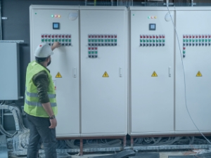
The customer approached Vishay when their existing panel potentiometer supplier discontinued production of a part used on an established and popular piece of equipment. To avoid a costly redesign, an existing panel potentiometer needed to be adapted to meet the customer’s electrical requirements. It would also have to fit the control panel insertion / retention envelope and existing markings, in addition to the PCB assembly attachment system.


DC-Link Capacitors With Tab Terminals For Harsh Vibration Profiles
Challenge
Our customer was evaluating a solution for power electronics equipment that required the use of several DC-Link capacitors on the same PCB, while ensuring that the devices would support critical vibration profiles. The products being considered for the application had a significantly high mass of around 100 g, and were attached to the PCB via four lead wires with 1.2 mm diameters. While testing these parts under severe vibration profiles, the customer reported broken lead wires. The challenge was clear: how can such high mass parts withstand severe vibration profiles, while maintaining a similar footprint on the PCB?
mmWave Loss and Unstable Performance in a Satellite Payload
Challenge
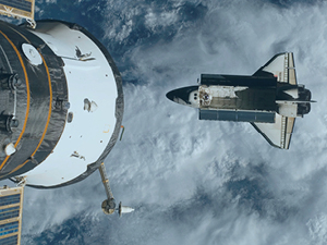
While developing a next‑generation Ka‑band and W‑band satellite payload for a low‑Earth‑orbit communications constellation, an RF systems engineer encountered an unexpected challenge. Although the team designed a GaN power amplifier and low‑noise receiver chain to operate above 80 GHz, system testing revealed significant performance degradation. The active devices met their specifications, but once the signal left the die, system performance collapsed: Insertion loss exceeded the link budget by 1.5 dB Parasitic inductance from wire bonds and interconnects distorted matching Board-to-board variation caused gain and phase inconsistencies across flight units Commercial passive components were too large and introduced resonances above 70 GHz The design relied on an advanced organic PCB with thick‑film passives and LTCC modules. Despite extensive tuning and redesign cycles, performance drifted from build to build, introducing unacceptable risk to schedule and qualification.
Have questions? We can help.
This is our general contact form. If you have more specific questions or needs please select from the options below.