
Fine-Tuning Assembly Processes With AuSn Patterning
Challenge
The customer’s optical transceiver design required the mounting of a laser diode on a substrate. The accuracy required when mounting this type of component, to ensure the laser output hits the lens and provides optimal performance, is largely unachievable using standard solder preforms and paste, as placement tolerances are very tight and are measured in mils (thousandths of an inch).
The final design would also need to withstand the temperature cycling testing required by the application.

Solution
The customer’s design had a pre-determined and specific location for the laser diode on the sub-mount and incorporated a resistor and edge-wrap patterning.
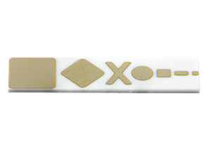
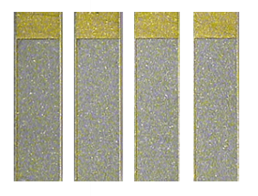
The Vishay EFI thin film manufacturing process is able to sputter AuSn up to a 7 µ layer with a tolerance of just 1 µ, and in a 15 mil by 15 mil square with tolerance of ± 0.5 mil, which is well below the customer’s initial design target of 1 mil.
The AuSn material is a purer eutectic solder material that makes it less susceptible to solderability degradation due to environmental issues like moisture. The alloy is also much thinner than solder paste and much more predictable, allowing it to be located much closer to the heatsink for further performance improvement.
For this design, the AuSn pad was deposited on the bottom side of the substrate, over the conductor layer, with 1 mil pulled back from the pattern edge.
This solved our customer’s problem because they are now able to fully automate the precision of their laser diode mounting process, without the need for additional preforms.
Benefit
The Vishay EFI high accuracy AuSn patterning enabled the fine-tuning of the end customer’s automated component placement and assembly processes to meet the most demanding design requirements necessary when incorporating high accuracy optical signals in a circuit.
In addition, Vishay EFI's 80/20 eutectic AuSn allows for better thermal transfer than traditional preforms.
Additional Case Studies
Avoiding a Complete Redesign After a Panel Potentiometer was Made Obsolete
Challenge
The customer approached Vishay when their existing panel potentiometer supplier discontinued production of a part used on an established and popular piece of equipment. To avoid a costly redesign, an existing panel potentiometer needed to be adapted to meet the customer’s electrical requirements. It would also have to fit the control panel insertion / retention envelope and existing markings, in addition to the PCB assembly attachment system.


DC-Link Capacitors With Tab Terminals For Harsh Vibration Profiles
Challenge
Our customer was evaluating a solution for power electronics equipment that required the use of several DC-Link capacitors on the same PCB, while ensuring that the devices would support critical vibration profiles. The products being considered for the application had a significantly high mass of around 100 g, and were attached to the PCB via four lead wires with 1.2 mm diameters. While testing these parts under severe vibration profiles, the customer reported broken lead wires. The challenge was clear: how can such high mass parts withstand severe vibration profiles, while maintaining a similar footprint on the PCB?

mmWave Loss and Unstable Performance in a Satellite Payload
Challenge
While developing a next‑generation Ka‑band and W‑band satellite payload for a low‑Earth‑orbit communications constellation, an RF systems engineer encountered an unexpected challenge. Although the team designed a GaN power amplifier and low‑noise receiver chain to operate above 80 GHz, system testing revealed significant performance degradation. The active devices met their specifications, but once the signal left the die, system performance collapsed: Insertion loss exceeded the link budget by 1.5 dB Parasitic inductance from wire bonds and interconnects distorted matching Board-to-board variation caused gain and phase inconsistencies across flight units Commercial passive components were too large and introduced resonances above 70 GHz The design relied on an advanced organic PCB with thick‑film passives and LTCC modules. Despite extensive tuning and redesign cycles, performance drifted from build to build, introducing unacceptable risk to schedule and qualification.
Have questions? We can help.
This is our general contact form. If you have more specific questions or needs please select from the options below.